Address
304 North Cardinal St.
Dorchester Center, MA 02124
Work Hours
Monday to Friday: 7AM - 7PM
Weekend: 10AM - 5PM
Address
304 North Cardinal St.
Dorchester Center, MA 02124
Work Hours
Monday to Friday: 7AM - 7PM
Weekend: 10AM - 5PM

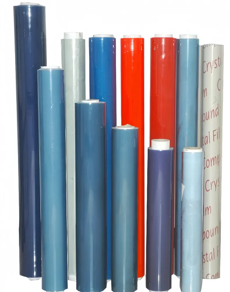
ITO (indium tin oxide) conductive film is a transparent, electrically conductive coating applied to plastic or glass substrates. It combines high optical transparency with low electrical resistance, making it a go-to material in touchscreens, displays, photovoltaics, and many sensor applications.
ITO is a metal oxide material that conducts electricity through a thin, continuous layer while allowing visible light to pass. Deposited by sputtering or other coating methods, the film’s conductivity depends on thickness, stoichiometry, and post-deposition treatments. In practical devices it acts as a transparent electrode that can carry signals or bias voltages without blocking the user’s view.
ITO conductive film is available in several forms depending on substrate and deposition:
Sputtered ITO on glass: High stability, used in large displays and solar modules.
Sputtered ITO on PET/PC: Flexible, used in foldable displays, flexible touch panels, and printed electronics.
Patterned ITO: Photo-lithography or laser-etched patterns enable interconnects, electrodes, and fine touch matrix traces.
Manufacturers choose ITO for several advantages:
High optical transparency with visible light transmission often above 80% for thin films.
Low sheet resistance (typically 10–100 ohms/sq depending on thickness) for reliable signal routing.
Good adhesion to many substrates and compatibility with cleanroom processes and microfabrication.
Scalability: Standard sputtering and vacuum coating lines support high volumes for displays and solar panels.
ITO conductive film appears in many products:
Consumer electronics: Touchscreens, OLED/LCD front electrodes, anti-static protective layers.
Renewable energy: Transparent electrodes for thin-film solar cells and perovskite devices.
Automotive & smart windows: Defogging, heated glazing, HUD touch surfaces.
Medical & industrial sensors: Biosensors, EMI shielding films, and capacitive sensors where transparency is required.
| Property | Typical Range | Impact |
|---|---|---|
| Sheet Resistance | 10–100 ohm/sq | Controls electrical performance and power loss |
| Optical Transmission | >80% (visible) | Determines display brightness and clarity |
| Thickness | 10–500 nm | Affects conductivity and flexibility |
| Substrate | Glass, PET, PC | Defines mechanical properties and end-use |
ITO films are typically deposited by magnetron sputtering. Critical process parameters include target composition, deposition rate, substrate temperature, and post-deposition annealing. These determine electrical and optical performance, as well as adhesion and durability.
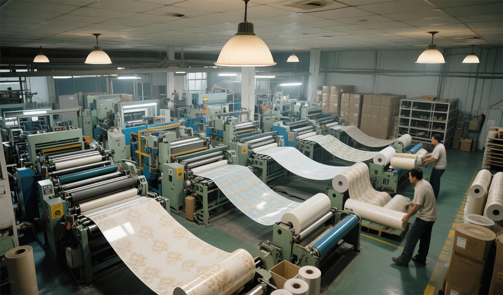
For reliable supply and consistent specifications, consider suppliers with in-house production control and multiple QC checkpoints. One such supplier in the PVC/decorative film space is Pulivk, which operates full in-house production lines and flexible OEM services.
When specifying ITO for a project, pay attention to:
Sheet resistance vs. transparency trade-off: Thicker films reduce resistance but lower light transmission.
Patterning tolerance: Define minimum line width and clearance if laser or photolithographic patterning is needed.
Environmental stability: Consider protective overcoats for humid or mechanically demanding applications.
ITO is not always the best choice. Alternatives include silver nanowires, graphene, conductive polymers (e.g., PEDOT:PSS), and metal mesh electrodes. Choose alternatives when extreme flexibility, stretchability, or lower-cost printed electronics are required. ITO remains preferred when high optical clarity and process compatibility are priorities.
To select the right ITO film:
– Define required sheet resistance and transparency.
– Choose substrate (glass for stability, PET/PC for flexibility).
– Confirm compatibility with patterning and downstream assembly.
– Request process documentation and QC data (sheet resistance mapping, adhesion tests, optical transmission).
Is ITO flexible? Thin ITO on flexible substrates can bend, but repeated flexing may crack the brittle oxide layer unless specially engineered.
How is ITO patterned? Typical methods include photolithography with wet etch, laser ablation, or selective deposition through masks.
What limits ITO lifetime? Mechanical cracking, environmental corrosion at exposed edges, and delamination under stress are common failure modes—mitigated by protective coatings and proper encapsulation.